When I mentioned that the tachometer cable for the Yanmar tractor needed to be almost 1/2 inch longer, Jim decided to try his MIG welding skills, before trying to obtain and modify the crimp-on extension mentioned yesterday. I was impressed that Jim was able to accomplish this without melting the tiny end of the cable off.
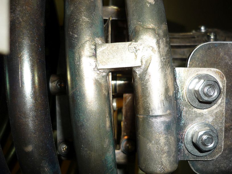
My job was to slowly and carefully grind the end back down to size making sure its cross-section was perfectly square. The standard dimension is about 0.100″ square. Upon getting it down to about 0.103″, it would just begin to slide into the tachometer connection. It was decided to leave it slightly oversize. Maybe it will not wear out as quickly. This is what it looked like when it was ready to install:
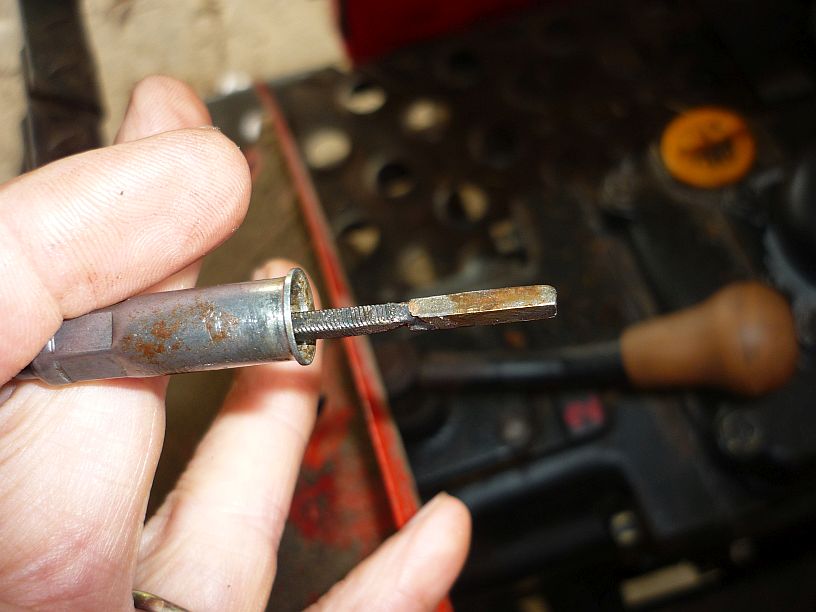
The repaired tachometer cable is now ready for try out.
The tractor was started and the tachometer worked, and continued working!
In the process of searching for a replacement tach cable, I discovered a valuable piece of information and passed it on to Mike and Jim. The John Deere 1050 tractor is the same as the Yanmar YM330D, except for the sheet metal (for the dash and engine cover). John Deere actually had Yanmar, a Japanese company, make the 1050, and some other models, for them. This might be useful to know when it comes to getting replacement parts for the Yanmar.

Yanmar YM330D tractor used for cutting the tall grass on the TWR Guam transmitter site.
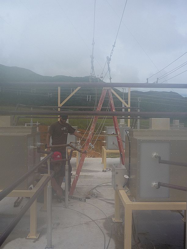
Shortly after we arrived, MIke asked me to look at a PA (power amplifier) coil that had been removed from the HC100 (100,000-watt shortwave transmitter we built in Elkhart). The spare inductor had been installed in its place, when they found some metal particles under this inductor, which indicated excessive wear somewhere. Because the inductor was heavy and on the floor in a very confined storage area, I asked Mike to help me get it out and set it on a table for ease of inspection. This inductor makes just over 5 revolutions from its extreme high frequency end to the extreme low frequency end. No obvious excessive wear could be found on either of the two rollers, nor on the coil where contact is made. In fact, the silver plating was still in good condition in all the contact areas.
It was found that it did take extra torque to turn the coil in a couple of places. Also noted that the contact rollers were not riding parallel to the coils of tubing in places. I decided to document the relative information in steps of 1/4 turn to see if there is any pattern to the anomalies.
This is the worst case of the roller not running parallel to the coil.
Near the end of the work day, it was determined that the problem of extra torque was caused when the idler rollers, that keep the contact rollers centered in the coil, contacted and began to push out on the inside diameter of the coil windings.
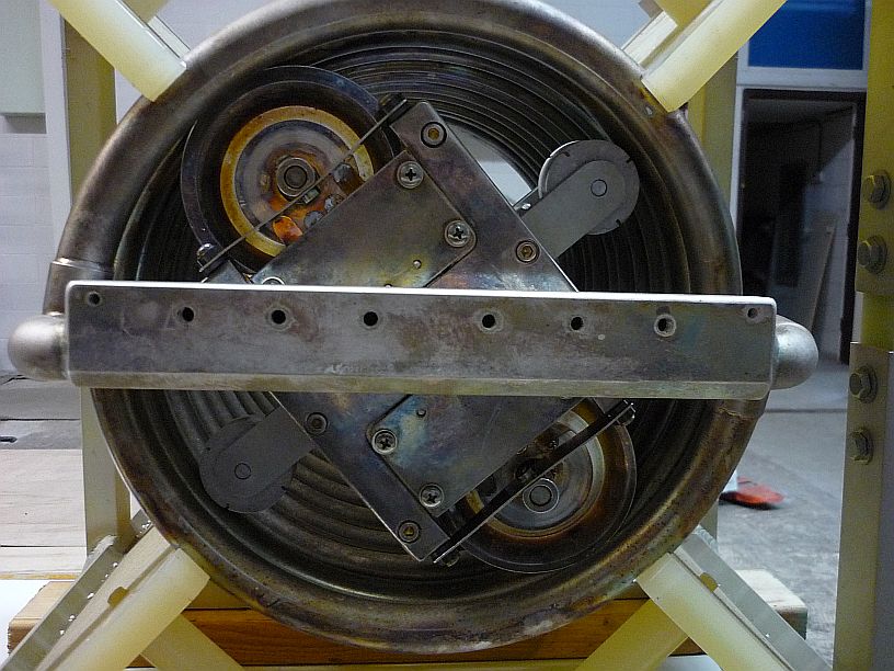
The idler rollers are the smaller white rollers seen here.