
First thing this morning, I noticed that Transmitter 2 (TX2) efficiency was back to normal, but no reason could be found! One of the ways of comparing the efficiency of like transmitters is to check their cooling water temperatures. They should be the same. Using a hand-held digital thermometer, I compared all three 100,000 watt transmitters. TX1 & TX2 readings were comparable and similar to their computer readouts, but TX3 read was about 15 degrees higher than its computer reading, which was comparable to the other two transmitters! When TX3 was shut off, the hand-held thermometer instantly returned to a ‘normal’ reading!! TX3 had been on 9500kHz. After it was retuned to 7315kHz, the reading was normal. This confirmed that the hand-held electronic thermometer is sensitive to certain RF frequencies, which can cause erroneous readings.
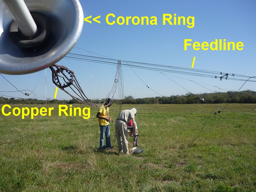
The copper ring shown here is the same as the ones used on the feedline
We made some adjustments to the feedline to Antenna 6 to see if the RF unbalance, when it is used on TX3, can be improved. The 300 ohm feedline consists of two conductors. Each conductor is made up of six wires spaced equally by 2 inch diameter rings (like the antenna element in the photo). On one of the feedline spans, the two top wires of the six were sagging, so we fabricated and added another ring, with clamps, to correct the sagging. When this was tested, there was no obvious improvement in the RF unbalance. We noticed that another span had two bottom wires of the six that were sagging. We cut two pieces of PVC pipe to temporarily pull these two lower wires into position Again, there was no noticeable improvement in VSWR or RF unbalance.
In the afternoon, it was decided to test TX3 on Antenna 6 on 7300kHz at full power with modulation and have observers under the antenna to pinpoint any arcing problems. After about 30 minutes we heard minor arcing and Graham spotted its exact location. This arcing was not enough to trip the transmitter off, but if left to continue, it could possibly flare up to a much bigger arc due to heating and ionization of the air at this high voltage point. This may be what has been happening in the evening to cause the transmitter to occasionally trip off due to RF unbalance. At about 2:45pm it was decided to quickly let the antenna down and investigate. We found that the arcing was between the corona ring and where it was attached to the element. The bolt was not making a very tight connection. The connection was taken apart and a file was used to clean up the surfaces. The corona ring was then bolted more tightly onto its radiating element. Everything was put back together and the antenna raised in record time — before 3:30pm. We just had time to bring up the transmitter and test the antenna before evening broadcasts began. I listened to the broadcast in the evening and heard no dropouts at all. Will have to verify this by reviewing the logs when we get back to the site on Thursday.
It was a really full day!!