The proofread copy of our August McGuiReport was returned to us, so I took a few minutes before work to make the suggested corrections and update our travel plan information, now that our air tickets have been purchased.
My first task of the day at the transmitter site was to document what was done on the PA inductor yesterday, and outline what still needed to be done, then submit this information to Mike. Hopefully, he can have the final improvements done to the coil, once the newer design of leaf springs arrive.
Mike wanted me to verify that TWR Guam’s vector impedance meter (VIM) was measuring correctly. This needs to be done to insure that it is ready to use when it becomes time to verify that the antenna switch matrix impedance is acceptable before putting the matrix into service.
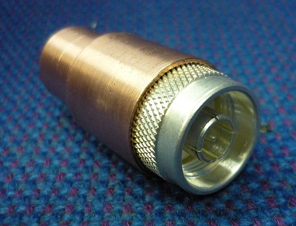
The probe of the meter has a very fragile tip, which is vulnerable to bending, or breaking. These tips are obsolete and very expensive to replace, if one can even be found. I was looking for a special connector that would protect the tip and connect directly to the N connector on the balun. [Since the transmission lines are unbalanced and the meter has a balanced probe, it is necessary to use a balun to get accurate measurements.] TWR Swaziland has this same model of VIM and it came with a kit of special connectors. Unfortunately, the special connector that I was looking for could not been found and no one was aware that there had ever been one.
After a bit of searching, I managed to find some parts to make a special connector using a type N cable connector and other parts in the transmitter stockroom and in a back room with plumbing fittings.

The first part found in the plumbing stock was a 3/4 to 1/2 reducer for rigid copper pipe. I was amazed — the large end was a perfect press fit over the N connector and the smaller end was a perfect sliding fit over the outside of the probe.
The next challenge was to make a contact for the tip of the probe. I remembered the connector pins that we replaced on the servo motors. One of these mated perfectly to the probe pin. The solder end of the center pin of the N connector, that is usually soldered to the center conductor of the coax cable, was then enlarged slightly — just enough for the connector pin (used for the servo motor) to be pressed into it. [Hope to have photos of this in our next blog entry.]
By now, it was quitting time, so we’ll plan to finish this tomorrow.
I did two projects after arriving at our apartment. The balcony walkway on our apartment tends to flood, especially when rain comes from the west. I managed to get two of three drains unplugged earlier, but the third one (nearest our door) seemed to be blocked with cement, It was probably never opened after the concrete forms were removed. I brought home a long punch this evening. After a couple taps with the hammer, a 1″ long plug of cement popped out and the puddle of water drained quickly. No more need to wade out of our apartment!
The second project was replacing the ceiling fan light switch in the second bedroom, where we do all our computer work. The light switch had gone bad, so we had picked up a replacement switch while in town on Sunday. After using a table lamp for the past week, It was nice to have plenty of light again!

