Our morning started off with a Skype conference meeting with the Human Resources department at TWR Cary headquarters. There were people from about 5 different locations involved in this meeting. I continue to marvel at what can be done using today’s technology!
After the meeting, I continued to work on the adapter to connect the VIM probe to the balun. This required some lathe work to make everything fit together.

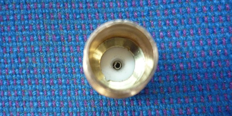
All the parts for assembling the connector, except for one — I still had to turn a plastic spacer on the lathe to hold the parts snugly together. The lathe was also used to make the ring in this photo and to shorten the other end of the connector to make sure the probe fit to the correct depth into its ‘socket’.

The spacer made on the lathe is being held in place here by the ring. Notches were made on the inner diameter of the ring to allow it to be tightened (or removed) using circlip pliers.

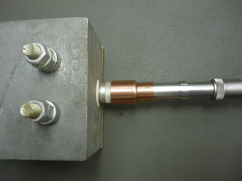
After the reducing coupling for copper pipe is pressed onto the connector, the adapter is complete. The probe can now be connected to the balun without danger of damaging the fragile probe tip.

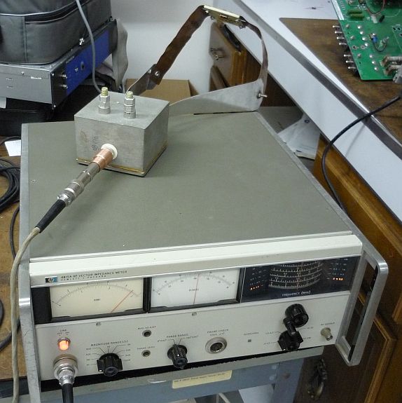
The Vector Impedance Meter and balun were now tested using the 300 ohm load. The readings were correct from 1 to 24 MHz. We can now be confident in the readings when the antenna switch matrix is finally measured to verify whether its impedance is correct.
We learned that the two containers, with the old transmitters, are supposed to be loaded onto a ship on 30 July. This means they should be picked up soon — preferably before this weekend’s anticipated rain.
